This article outlines the basics and principle behind Die RAID and how it is used to strengthen error correction in Solid State Drives (SSD). With Die RAID the onset of read retry can be delayed due to the additional layer of decision making in determining bit values. This means an increase in data integrity and a more stable device lifespan.
Introduction:
Error correction is an essential function in all storage and memory products. Whether it is due to products nearing its lifespan or stray cosmic radiation, error bits will always occur. As Moore’s Law has pushed our semiconductors to ever-smaller sizes, and the need for capacity brings more bits into every available space, the problem of error bits has only increased with the years. Without any countermeasures, this would see modern NAND flash devices fail after a relatively short amount of time.
This is where Die RAID comes in as one of the tools to combat error bits and is also one the reasons why some Solid State Drives (SSD) seemingly have capacities below the standard powers-of two table. The SSD will save some space for parity data used to fix any error bit that other error correction features have failed to mitigate. This is why Die RAID in combination with other error-correcting functions such as LDPC is one of the strongest methods available to increase Program/Erase (P/E) cycle numbers and ensure long-lasting flash performance.
Background:
BCH Code: The BCH code is a popular error correction method used in NAND flash, as well as satellite communication that utilizes hard decision making. BCH reached near ubiquity in the SSD market due to its effectiveness. However, due to recent limitations in light of NAND flash technology advancements, it is being replaced by Low-Density Parity Check (LDPC) as the favored ECC method for SSDs.
LDPC Code: is currently the standard ECC function for most SSDs. It has a stronger error correction capability compared to the BCH code. It uses soft decision making which simply explained allows for more accurate identification of the original bit string after an error has occurred.
Redundant Array of independent drives (RAID): RAID describes different methods of arranging two or more storage drives to ensure data integrity (and/or better performance). For data integrity purposes, this can be done by mirroring, striping, and storing parity data. Mirroring copies data from one drive to another ensuring that one set of data is available even if the other drive fails (RAID 1). Parity data is used in configurations of three or more drives that stores one set of parity data on one drive that can be used to recover data from any other drive that fails (RAID 5). Striping describes how data sets are written across the different drives, as opposed to storing it all on one drive.
XOR Function: The XOR function describes the basic way a parity bit is decided:
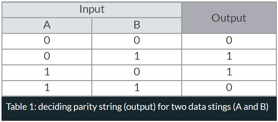
The parity bit is decided on the input. When the input differs (01, 10) the parity is true (1), giving an output of 1. The parity bit is false (0) if the input is the same (00, 11).
Let’s use an example to see how the parity bits between three 7-bit sequences is calculated:
String 1: 1010011
String 2: 1111001
String 3: 1101100
Parity: 1000110
If the data from string 1, 2 or 3 is lost it can be reconstructed using the parity string, this logic can be used to add further strings of data. This is called even parity, as the input (3 numbers) plus the parity bit always gives you an even number of ones. If you look at the last number of each string (1100), i.e. the last column, you can see that the input already has two ones, making the output 0. This also means that if there ever is a column with an odd number of ones, an error has occurred when transcribing the data.
Challenges:
Increasing rate of error bits: Decreasing the physical size of NAND flash cells enables us to add more cells per unit of area, which gives us an increased capacity per IC. However, it also leads to a greater risk of interference to the trapped charge inside the cell, which in turns leads to the rate of error bits growing. This is further compounded as each cell is made to hold more bits, which means that the buffer between each voltage level decreases and read errors are more likely to occur. For example, an MLC cell has to separate between 4 voltage levels (00, 01, 10, 11) while TLC cells separate between 9 (000 → 111).
Solutions:
This section will detail how Die RAID works and why it is a valuable addition to a standard LDPC ECC solution.
Die RAID Principle: Die RAID follows the same principle as standard RAID does for storage drives (RAID 5). Instead of data being striped across drives, Die RAID stripes data across different die with one parity buffer being added to each set. The principle is explained in the figure below:
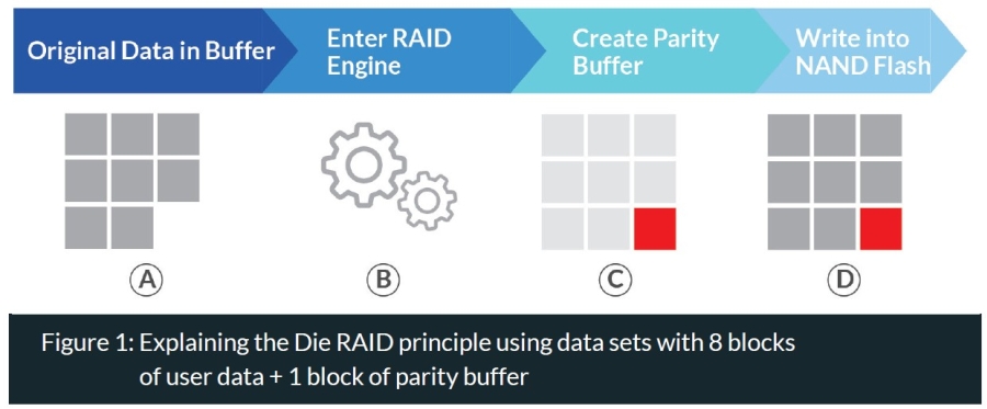
In the example above, we first have data received by the SSD (A) equal to 8 blocks. This enters the RAID engine (B) which adds a block of parity data (C) which then makes up the complete data set ultimately written to the SSD (D). This data set is then written across all die in what is called Super Blocks.
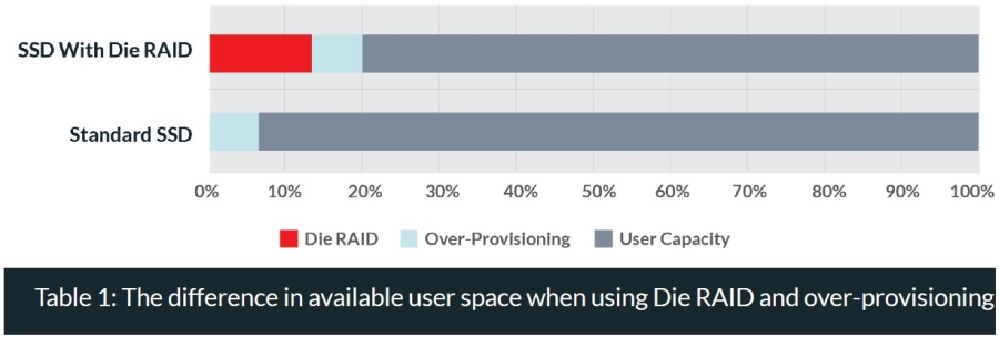
Along with over-provisioning, Die RAID will take up a certain amount of space on the SSD. The below chart shows an example of the distribution difference between an SSD with Die RAID and a standard SSD.
The Die Raid Process: the RAID engine located within the controller is what is deciding how to store that data received by the SSD. The engine constructs the RAID strips and will also run RAID recovery if error bits are detected and other ECC functions fail to mitigate the problem. That is to say, once the command to read data is sent, it first goes through the LDPC engine (see the figure below). If the data is correct or any error bit(s) is corrected by the LDPC engine the data is read without problem. If the LDPC engine is unable to correct the error bit, the Die RAID engine will run RAID recovery fixing the error, or if unable, mark the block as bad.
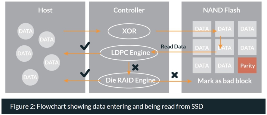
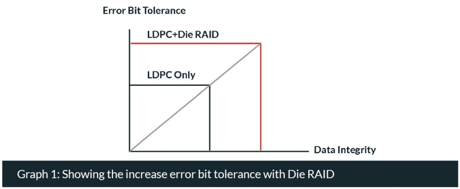
What this means is that Die RAID acts as an additional layer of defense against error bits, and will ultimately increase the lifespan of any SSD. Which is why it is recommended as default for any SSD to delay the onset of read retries and increase the overall P/E cycle number (see the graph below).
Conclusions:
Seeing that some capacity on the SSD is reserved for error correction can be confusing at first. But when one understands the need for SSD endurance, especially in the industrial field, Die RAID goes a long way in ensuring increased lifespan and higher overall data integrity. This is why we recommend including Die RAID for any application that sees moderate to high amounts of data workloads to ensure that the SSD can continue to deliver continuous performance in the long run. Innodisk solid state drives based on 3D TLC technology integrate the Die RAID technology.


